Alfatech Vietnam Co., Ltd


Assembly and Kinematic (Part 3)
Assembly and Kinematic (Part 3)
Step 4: Positioning the components (continute)
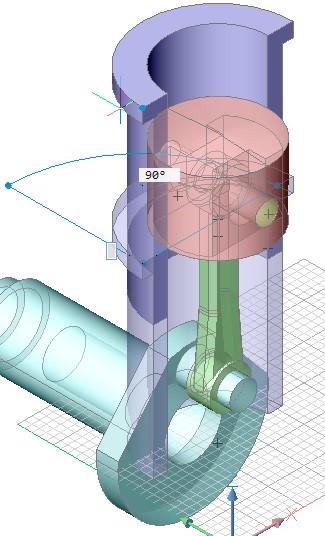
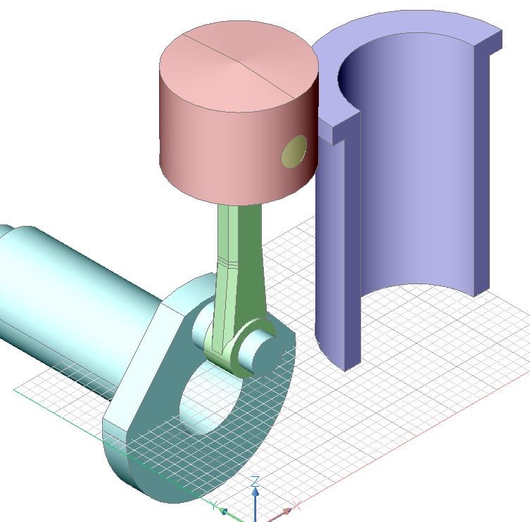
The connecting rod is automatically moved to the right position according to our design intent.
- Click the Concentric tool button (
 ) on the 3D Constraints toolbar.
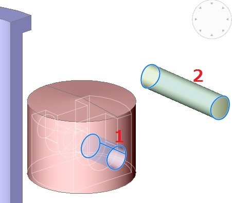
The command bar reads: Select a pair of subentities: - Move the cursor over two cylindrical faces of the piston (1) and the pin (2) as indicated in the image below.
Hit the TAB key until the correct face highlights, then click and move the cursor to the second face.
- Click the Tangent tool button (
 ) on the 3D Constraints toolbar.
The command bar reads: Select a pair of subentities: - Move the cursor over two cylindrical faces of the piston (1) and the pin (2) as indicated in the image below.
Hit the TAB key until the correct face highlights, then click and move the cursor to the second face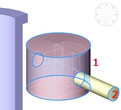
- Click the Coincident tool button (
 ) on the 3D Constraints toolbar. The command bar reads: Select a pair of subentities:
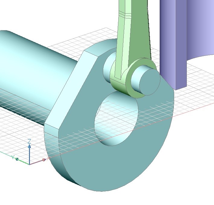
Move the cursor over two planar faces of the connecting rod (1) and the piston (2) as indicated in the image below.
Hit the TAB key until the correct face highlights, then click and move the cursor to the second face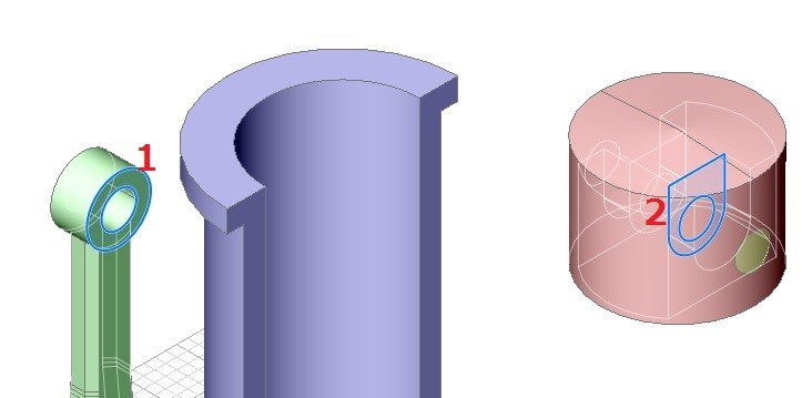 13. Click the Concentric tool button (
![]() ) on the 3D Constraints toolbar.
) on the 3D Constraints toolbar.
The command bar reads: Select a pair of subentities:
14. Move the cursor over two cylindrical faces of the connecting rod (1) and the pin (2) as indicated in the image below.
Hit the TAB key until the correct face highlights, then click and move the cursor to the second face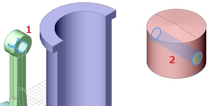
 15. Click the Concentric tool button (
![]() ) on the Constraints toolbar.
) on the Constraints toolbar.
The command bar reads: Select a pair of subentities:
16. Move the cursor over two cylindrical faces of the piston (1) and the cylinder (2) as indicated in the image below.
Hit the TAB key until the correct face highlights, then click and move the cursor to the second face.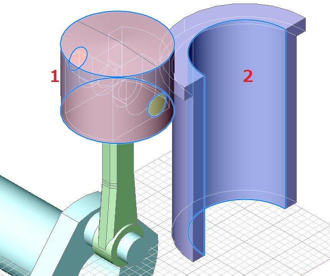
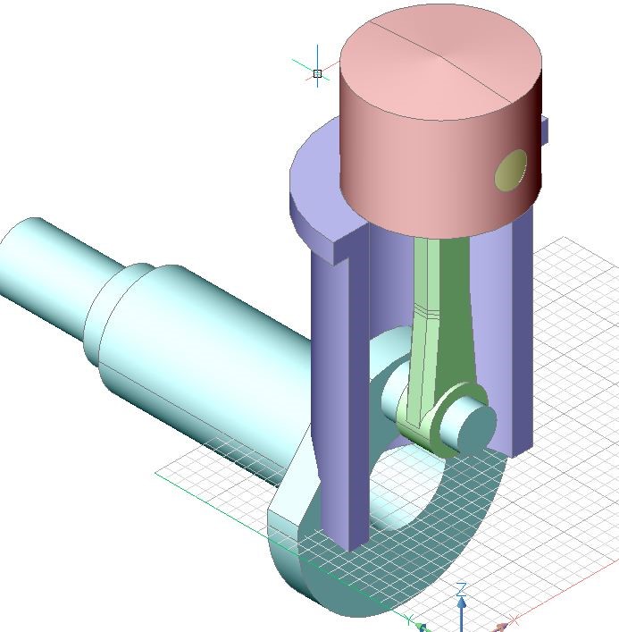
17. After applying the previous constraint it might be necessary to correct the position of the cylinder.
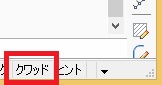
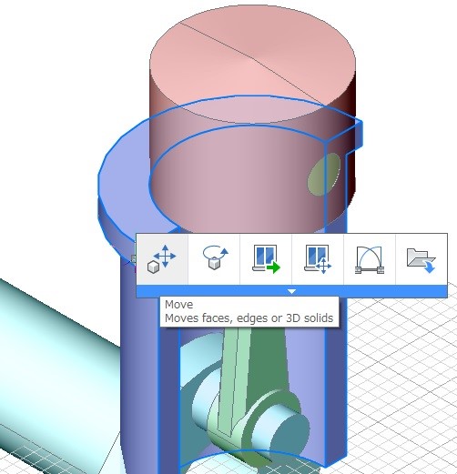
Move the cursor over the cylinder, then choose Move (![]() ) in the Quad cursor menu.
) in the Quad cursor menu.
The command bar reads: Enter base point <0,0,0>:
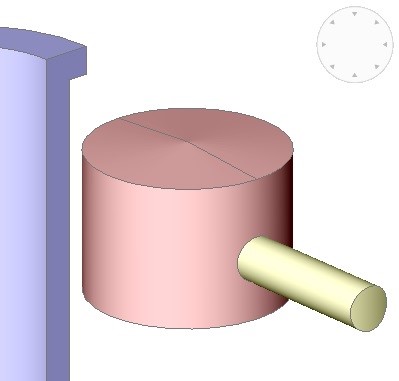
18. Use an entity snap (e.g. Endpoint) to specify the base point for the move operation on the cylinder.
The cylinder now moves dynamically with the cursor.
19. Hold down the Shift key to move the mouse cursor along the Z-axis.
Click to position the cylinder as shown in the image below.