Alfatech Vietnam Co., Ltd


Assembly and Kinematic (Part 2)
Step 3: Adding the components
- Click the Insert Component tool button (
 ) on the Assembly toolbar.
The Insert Mechanical Component dialog displays:
Open the
C:\Program Files\Bricsys\BricsCAD V16 vi_VN\Samples\Mechanical\piston folder.
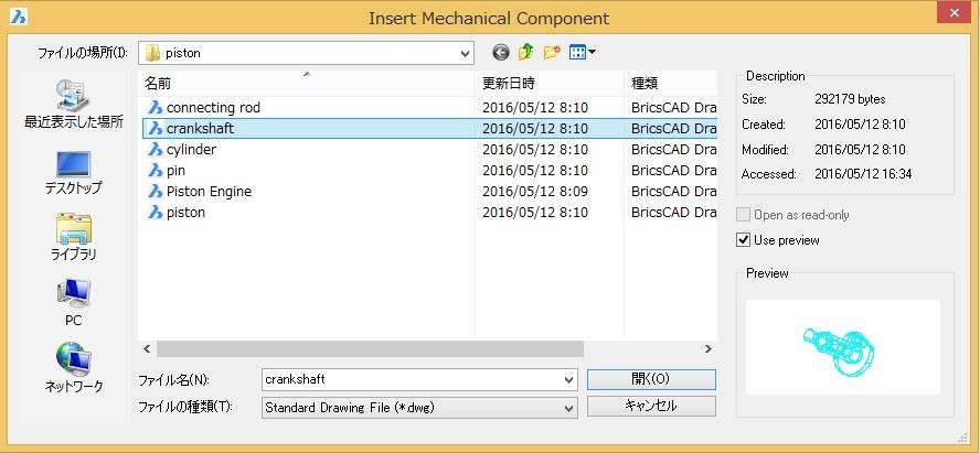
- Select the crankshaft.dwg, then double click or click the Open button.
The component is attached to the cursor with its origin point.
Dynamic dimensions display: Distance from the origin of the current coordinate system and angle from the X-axis. - We will consider the crankshaft as the anchor component of the assembly, and therefore insert it at the origin (0,0,0).
Please make sure the insertion point is exactly at 0,0,0, otherwise the kinematic analysis in step 6 might fail.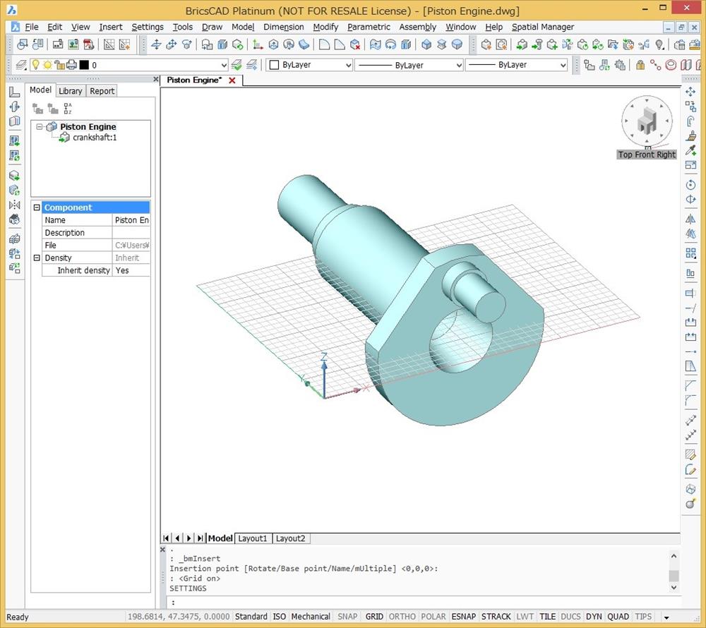
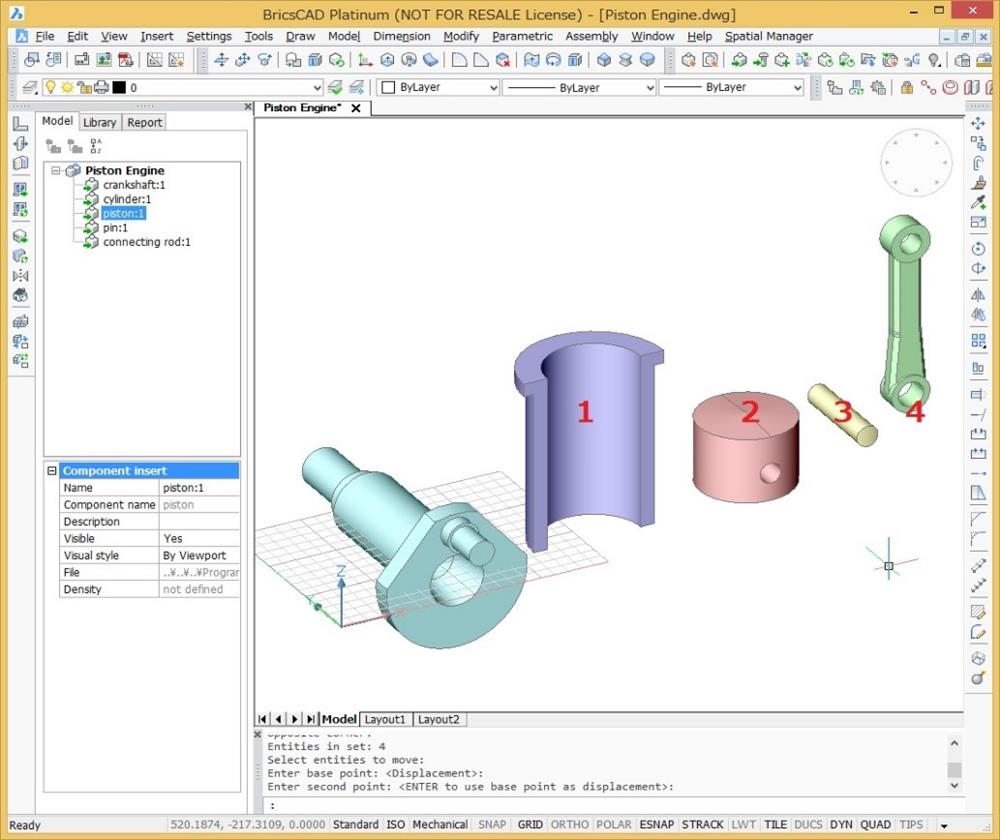
- Use the tools on the Look From toolbar to adjust the view orientation.
- Repeat the previous steps to insert the other components: cylinder (1), piston (2), pin (3) and connecting rod (4).
Step 4: Positioning the components.
- Click the Fix tool button (
 ) on the 3D Constraints toolbar.
The command bar reads: Select an edge, face or 3D solid: - Move the cursor over the crankshaft, then click to chosse
The position of the crankshaft is now locked, as indicated in the Constraints tree in the Mechanical Browser.
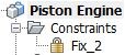 Clicking the constraint highlights the solid, face or edge it applies to.
3. Click the Concentric tool button (![]() ) on the 3D Constraints toolbar.
) on the 3D Constraints toolbar.
The command bar reads: Select a pair of subentities:
4. Move the cursor over two planar faces of the crankshaft (1) and the connecting rod (2) as indicated in the image below.
Hit the TAB key until the correct face highlights, then click and move the cursor to the second face.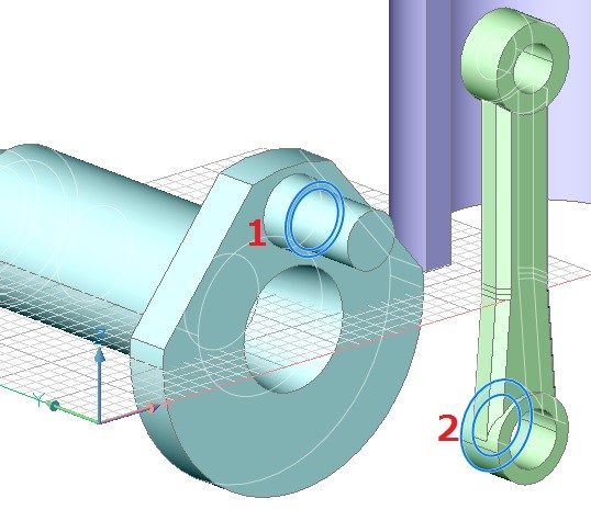 5. Click the Concentric tool button (
![]() ) on the 3D Constraints toolbar.
) on the 3D Constraints toolbar.
The command bar reads: Select a pair of subentities:
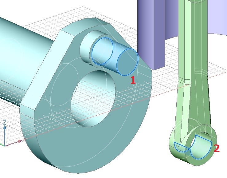
6. Move the cursor over two cylindrical faces of the crankshaft (1) and the connecting rod (2) as indicated in the image below.
Hit the TAB key until the correct face highlights, then click and move the cursor to the second face.
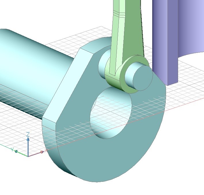
The connecting rod is automatically moved to the right position according to our design intent.
(To be continute)