Alfatech Vietnam Co., Ltd


Assembly and Kinematic (Part 4)
Step 5: Preparing for the kinematic analysis
The piston is correctly positioned inside the cylinder and connected to the crankshaft by the connecting rod.
We will now fix the distance between the cylindrical face of the crankshaft and the lower face of the cylinder by applying a dimensional constraint.
- Click the Distance tool button (
 ) on the 3D Constraints toolbar.
The command bar reads: Select a pair of subentities: - Select the cylindrical face of the crankshaft (1) and the lower planar face of the cylinder (2) as indicated in the image below:
The command bar reads: Enter distance value:
A dynamic distance entry field displays.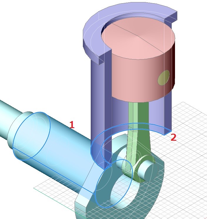
- Type 110 in the dynamic entry field.
The lower face of the cylinder is now fixed at a distance of 110 from the cylindrical face of the crankshaft.
We will fix the cylinder at its current position:
- Click the Fix tool button (
 ) on the 3D Constraints toolbar.
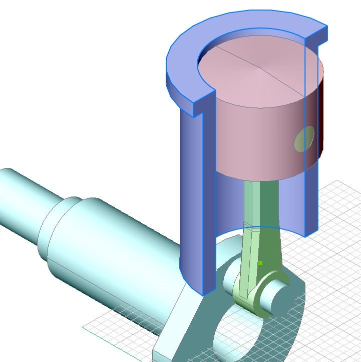
The command bar reads: Select an edge, face or 3D solid: - Move the cursor over the cylinder, then hit the TAB key until the body of the cylinder highlights as a whole (see image below).
In step 4.1 we have applied a fixation constraint to the body of the crankshaft, which removes all degrees of freedom from the crankshaft. To make it possible to rotate the crankshaft around its axis, it is necessary to remove this constraint and replace it by two fixation constraints: one to the cylindrical face of the crankshaft and one to its planar outer faces.
- Click the Fix tool button () on the 3D Constraints toolbar.
The command bar reads: Select an edge, face or 3D solid:
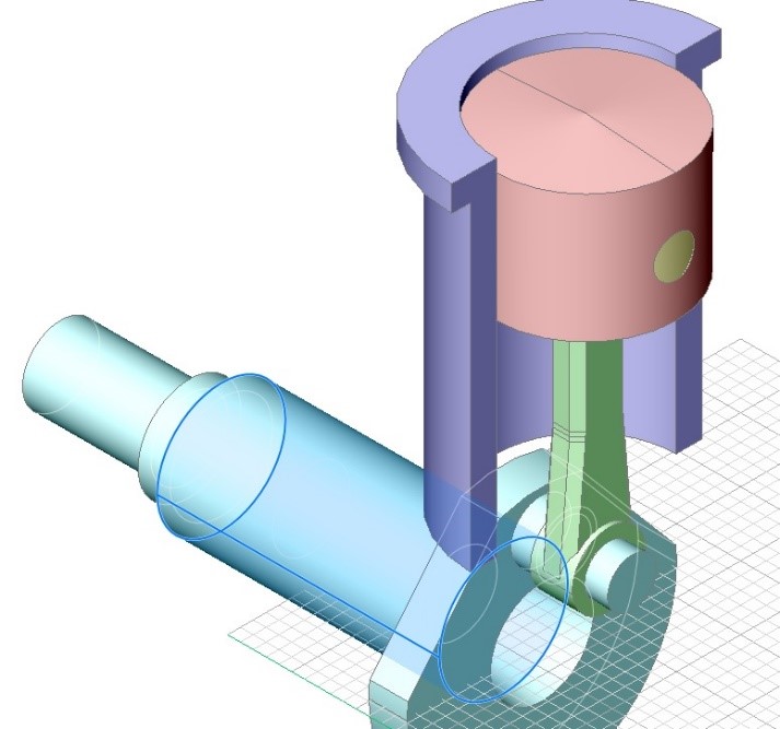
Move cursor over the cylindrical face of the crankshaft, then click (see image below)
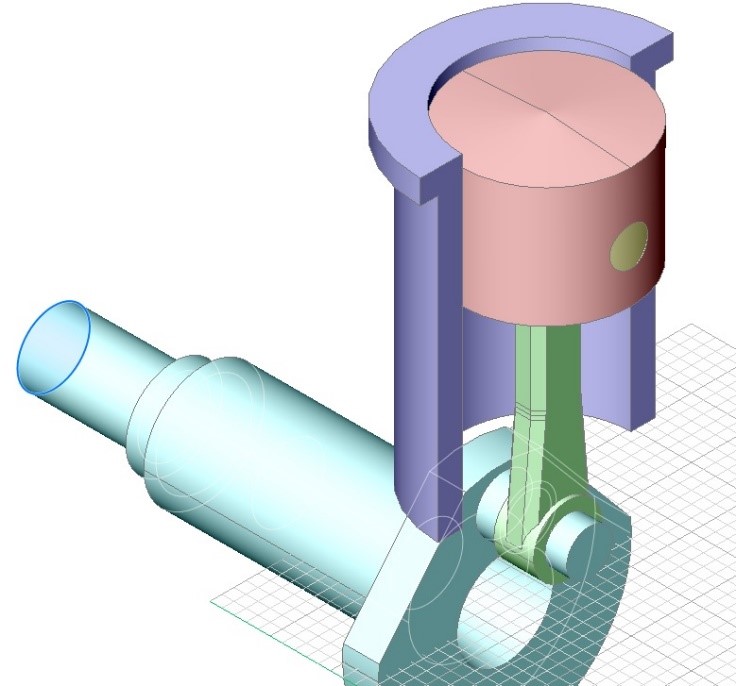
Repeat the previous steps for the planar outer face of the crankshaft (see image below).
- Select the Fix constraint applied in step 4.1 in the Constraints tree in the Mechanical Browser.
Right click and select Delete in the context menu.
In this assembly the crankshaft is the driving component. To run the kinematic analysis we will rotate the crankshaft around its axis, which in this case is the Y-axis of the WCS.
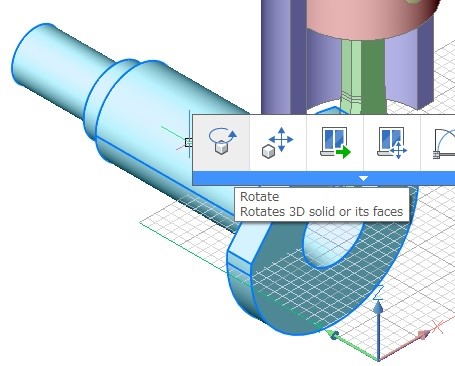
- Move the cursor over the crankshaft, then choose Rotate (
 ) in the Quad cursor menu
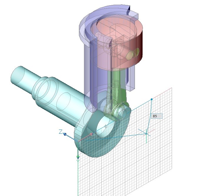
The command bar reads: Select axial entity or define axis by [2Points/Xaxis/Yaxis/Zaxis] <2Points>: - Do one of the following:
- Type Y, then press Enter.
- Choose Y axis in the prompt menu.
The command bar reads: Pick start point in the rotation plane:
- Pick a point in the drawing, then move the mouse to define the rotation angle.
The piston and the connecting rod move dynamically along with the rotation of the crankshaft, while the cylinder stays at its fixed position.
(The End)